
How to build a BSP Falcon Pro F2 chassis
To build the kit you will need: .032 wire, .062 wire, and .032 id brass tube. The building of any slot car chassis requires care. Please ensure that you wear protective eye glasses and only use tools in the recommend way. Soldering should be done in a well ventilated area. Recommended in the build of this chassis are BSP 'licky' brians flux, Hakko Soldering iron and Toro for cleaning the chassis. Some additional recommended parts are a Koford 10t pinon, a BSP 30t gear, Champion low friction oilites, or BSP Ceramic Ball races, JK Blade guide, and .062 top hats.
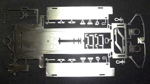
The kit of parts should look like this. clean up all the slots and then remove the parts carefully from the sprew. Keep them safe!
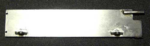
The damper rails need to be cut away where the tags are holding them to the motor box. Once you have done this make sure the centre section is VERY flat. Bend and tweak if needed. The damper rails need to spaced away from the main box rails.
Insert and solder in place the front pan hinge/stops .
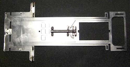
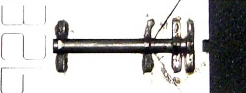
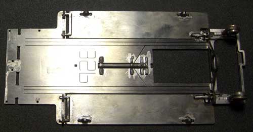
The centre spine is made up using .062 wire (1.6mm), and 4 eyelets. Ensure the wire can rotate before you solder them in. Once in place and the wire and motor box eyelets are soldered check the spine wire is level. The wire is soldered to the eyelets in the motor box.
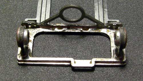
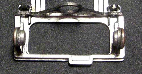
Next build up the rear end of the chassis. The motor locater, which also includes the up stops for the damper rail and the pans. I put oilites in the pillow blocks, before putting them in the slots. With the motor located held in place, slide the rear brace into position. This should interlock with the pillow blocks and the motor locater. Put an axle through the oilites,to ensure the pillow blocks are upright. Solder the parts together making sure the parts are flat , or at 90'.
Build up the pans with the 2 pin-tube holders and the rear stop. Do NOT attach the front stop.
Using .032 wire through the hole in the damper pan stop, solder the wire and the part in place. Make sure the damper rail is level and does not drop below the chassis once you have done this.
The pans are located as shown. The pan should not drop below the chassis at the back. Adjust the stop on the pan if needed. The front stops are lined up using the .032 holes and some wire. The pans should not drop below the main centre at the front either.
This next stage is VERY important to get right.
Do the next stage in this order, but do not solder until the end:
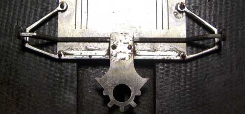
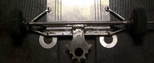
Locate the suspension with 4 pieces of .032 wire
Locate the uprights in the suspension.
Locate the front axle support.
Locate the guide tongue using 2 piece of .032 wire.
Now solder the 4 suspension locators, and the guide tongue in place.
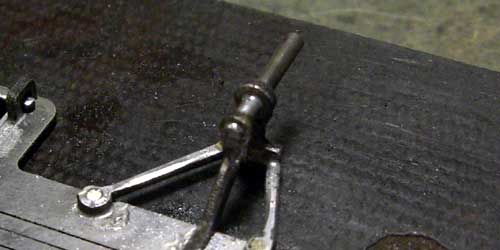
Now the axle. Pass the axle wire (.062) across the width of the chassis through the uprights. Using the wheels that will be used on the car you can set the height. On this chassis I have set ride height at .005 using some guide spacers under the main chassis.
With all this in place, solder the axle supports, the uprights (top and bottom) and the axle into position.
Trim the axle and add the strengtheners. Slide them from the inside over the axle and solder to the axle and the support. Clean the chassis thoroughly with the Toro and scrubbing brush.
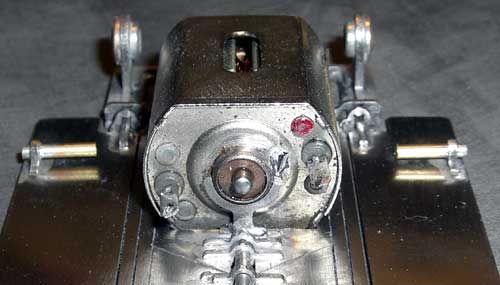
Drop the motor into place and add the front motor support. The motor will not fit if this soldered in first.
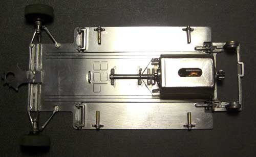
Using some 'top hats' or brass tube as a retainer for the front wheels finish the front axle. Add the lead wire keeper and give the chassis a good scrub with soap. The car is very light, so will need some additional weight. Lead placement will depend on driver preference and track.
Recommended set up is: JK Hawk 7 or Proslot Mini can , with around 10/30 gearing, BSP tyres and a CAT RB1 F1 bodyshell.