How to build a BSP 1/24 Eurosport.
To build the kit you will need: .032 wire, .032 id stainless steal tubing, .032 id Brass tubing. Building of any slot car chassis requires care. Please ensure that you wear protective eye glasses and only use tools in the recommend way. Soldering should be done in a well ventilated area.
The order I build the chassis is not the only way, but is a method I have come to from building many chassis.
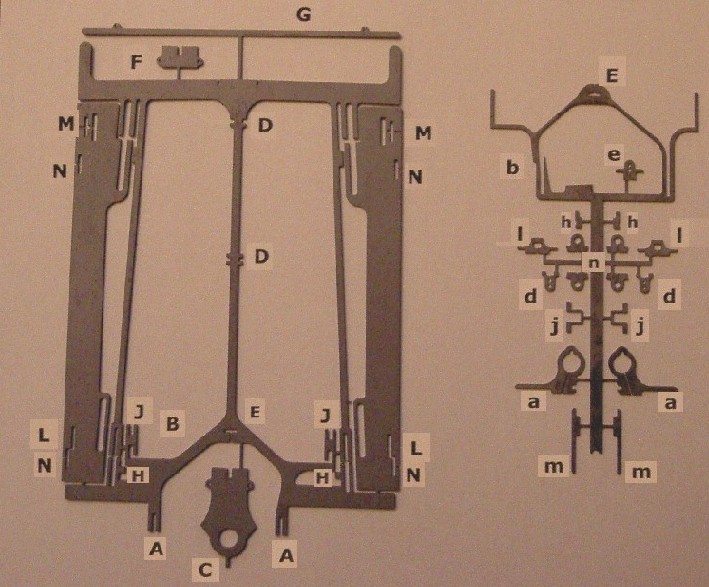
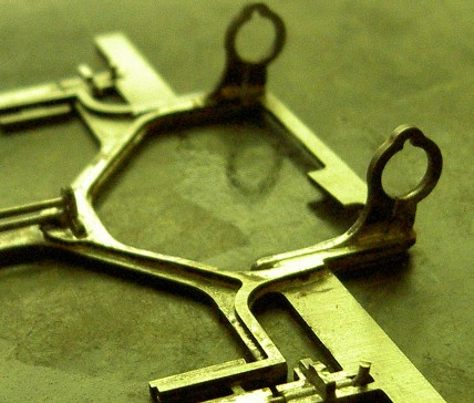
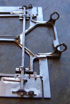
Below is a picture of the chassis frame. The pieces locate into the slots marked with corresponding letter.
Stage one is to clean up the chassis and all the slots. Use a diamond file if possible.
Stage two is the remove all the parts from the sprew and keep them safe!
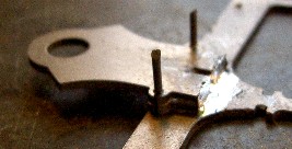
Next is to attach the guide (C) and spacer plate (F). Use the locating holes and 2 small lengths of .032 wire.
Next move down the spine and put in the spine supports d into the D slots. If you intend to use a wire retainer and a cross wire to stop leadwires dropping through the chassis, do it NOW.
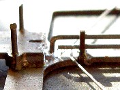
At the back of the chassis insert the pillow blocks (a) into place and the motor box brace (b) over the top of the chassis. Place (e) through the brace and into the main chassis. Before soldering into place, put some oilites into the holes and make sure the centre of the axle to the centre of the guide pivot DOES NOT exceed 125mm. This is a LEGAL requirement of the class. I solder the brace at the front of the motor box first. This allows me to ensure that the rear axle is square to the chassis and within the 125mm maximum length. Once you are sure everything is positioned correctly, solder it in place.
The spine is double stacked .032 wire.They pass through the 3 uprights (d x2 and e).Bend the top wire as shown and solder the wires into the guide plate first, then to e, ensuring that, as the joints cool the chassis remains FLAT.
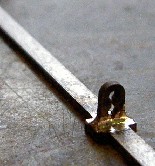
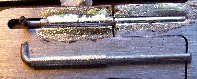
The ‘rails’ need to be connected to motorbox. 2 pieces of .032 wire and stainless tube. Bend and cut as shown.
 Solder the tube first, and make sure the wire still moves freely. At this point
place h over the soldered tube and the supporting chassis part and solder. This stops
the pan 'hooking up'. Then solder the wire to the rail in its forward most position.
Solder the tube first, and make sure the wire still moves freely. At this point
place h over the soldered tube and the supporting chassis part and solder. This stops
the pan 'hooking up'. Then solder the wire to the rail in its forward most position.
Now leave the centre section and build up the pans. This a case of inserting the relavant pieces in the correct holes.
At this point should have only 2x J , the cross bar (G) pieces left.
Now clean the chassis thoroughly.
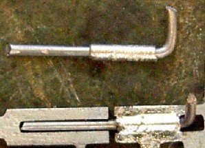
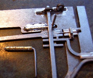
To attach the pans you need 2 small pieces of the stainless tube and .032 wire. Bend the wire as shown.
Make sure the pan will move back and forward. I restrict rearward movement by .010 from maximum.
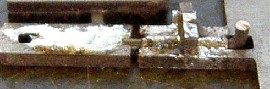
The rear of the pans and the movement is controlled by the cross bar. It is important that the cross rests on the horns on the front of the motor box, and that the pans sit flat while the cross bar is in position. Check this before soldering. The rear hinge is similar to the front, but is made using the brass tube. Once the hinge is made pass it up from under the chassis and through the hole in the cross. Solder the tube to the pan once this done, but be sure to check that the pan can still move freely. Do this to the other side.
Once both hinges are soldered to the pans, put both pans is the most rearward position and solder the wire that travels up through the cross bar. Ensure all parts move freely and solder the j parts into J.
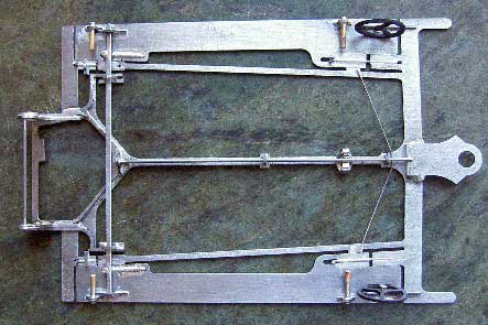
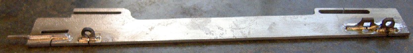
When you put in the rear axle bearings, put in a wire brace at the top on the bearing holes. To add front wheels, bend a pin and solder in the hole at the front of the pan, and lastly add the pin tubes. The finished chassis should look like this. Now go winning!