
How to build a BSP GT12-10 Chassis.
To build the kit you will need: .062wire, or .032 wire, .032 id and .062 id brass tubing. Building of any slot car chassis requires care. Please ensure that you wear protective eye glasses and only use tools in the recommend way. Soldering should be done in a well ventilated area.
The order I build the chassis is not the only way, but is a method I have come to from building many chassis. Please note that this kit is a pre prod version, and the production version will be slightly different.
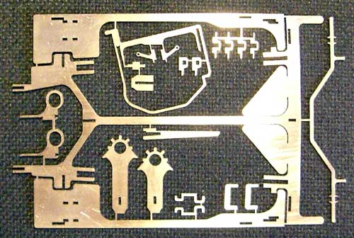
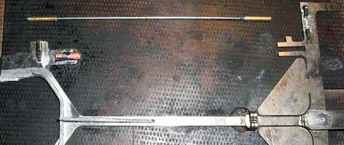
Pictured below is the Kit. Before assembling, clean up all the slots and cut the pieces from the main chassis.
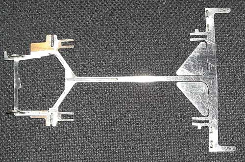
Once you have the main centre section you can start to build up the chassis. Before you do ensure the chassis is flat, and square. Then add the pillow blocks, the spine stiftener and the motor box support (ensuring the pillow blocks are upright and square to the chassis), the cross bar stops, and the front hinge hoops.
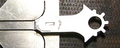
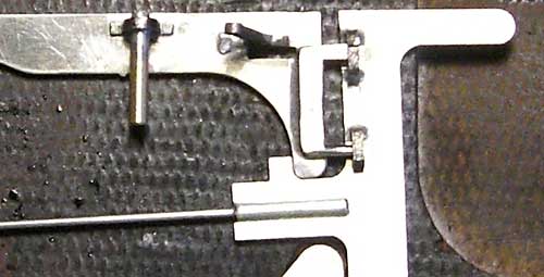
Next move to the front and add on the guide plate locator and spacer.
and then the guide plate. Be very sure the guide plate is level and well soldered. There are 2 guide plates supplied. The chassis is legal for GT12 with both guide plates, but for OG12 you must use the shorter one.
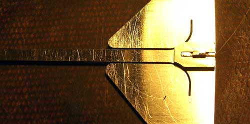
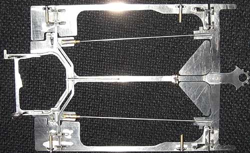
The centre section is finished with the addition of the rails. The rails are either .062 wire (which will fit directly into the tube at the rear) or .032 wire with .032 id tube sleeve fitted at either end (as shown) and they sit in .062id tubing at the rear. Solder .062id the tube first.
This will make sure the wire can move in the tube. Slide it into the tube and solder at the front.
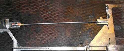
The Centre section is now complete. Move onto the pans.
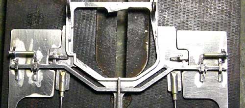
Put the 4 pin tube holders into the slots and solder into position, along with the out cross bar stop. The additional front wheel support is NOT Submitted for USRA GT12 use as the rules no longer require the cars to have front wheels, but you they are need for OG12. Then lay the pan in position, and slide the hinge part through the loops and locate on the pan. Solder in place.
The next task is to attach the cross bar. This will require you to grid the .062 tube a little to ensure that you can fit and remove the cross bar at a later date. The cross bar fits as shown. The inner pan stops are soldered in place once the cross bar is set up. Make sure the cross keeps the pans from dropping below the chassis, but also does not hang the pans up. Tweek cross bar if needed. Once the inner the stops are soldered to the pans the chassis, give the chassis a good scrub and clean.
Make sure the pans are moving smoothly, the rails are not soldered up at the rear, and add pin tubing and lead wire retainer. Use 2 gears of the same height to check the axle is level, and solder in the bearings. From 2009 onwards, ball bearings are legal in the axle.
Now go racing!!